Situation
You are a manufacturer of production machinery (e.g. CNC machines) and are considering the final assembly/final commissioning (end-of-line/FAT) stage of the machine within your production process.
In doing so, you are often faced with the following typical conditions:
The machine, including the network components, is already fully wired and pre-configured
The final network configuration (customer network, machine network(s), remote maintenance access) has been set up or, at the very least, prepared
Access to the machine is necessary for:
Final tests and FAT
Diagnosis
Final parameterisation
The following challenges further complicate the situation:
Access via factory network is difficult to achieve
IT restrictions, a lack of integration and customer-specific requirements (IP addresses, etc.) prevent this
Access via wired machine network is difficult to achieve
Requires physical connection
Risk of affecting the final configuration (IP conflicts, routing, security)
Additional cabling work (temporary switches, patching)
The objective is to provide temporary, secure access to the machine ( the machine network)
without making any changes to the existing network structure and
without affecting the final configuration.
Solution
Using an INSYS icom Wi-Fi-enabled industrial router from the MRX.neo or MOROS.neo series to provide temporary Wi-Fi access with the following features:
Wi-Fi is disabled by default
Activation is carried out deliberately using a physical button
Automatic deactivation via timeout
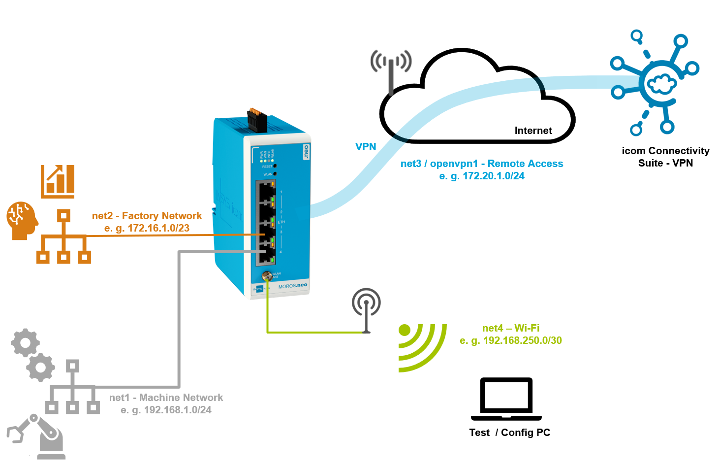
Please note that the networks are separate!
In our example, the Wi-Fi forms a separate, logically isolated service network. It is intended to allow access only to the local machine network.
Prerequisites
This Configuration Guide assumes that the following infrastructure or configuration is already in place:
A remote maintenance solution has been configured (optional, but recommended) ✔
see the Configuration Guides for our icom Connectivity Suite – VPNRouters and network components are pre-configured (staging) and integrated into the system ✔
Access to the router is available (e.g. locally or initially) ✔
Restrictions
There are no significant restrictions.
Recommendations
Configure the Wi-Fi exclusively as a temporary service interface, you may, if you wish, remove these completely from the configuration once commissioning is complete.
Set a timeout that allows sufficient time for your commissioning processes (e.g. 30–45 minutes).
Use a separate IP subnet for the Wi-Fi and set the subnet mask and DHCP server settings to cover only a small network (e.g. 192.168.250.0/30).
Restrict access via firewall rules and only allow relevant ports and protocols.
Give the Wi-Fi network a unique SSID (e.g. SERVICE_<plant_number>). The factory default SSID is MOROS.neo or MRX.neo, followed by the router’s serial number.
Procedure
Follow the steps below to configure the router, which connects the machine to the machine network, the remote maintenance service or the internet, so that it provides a temporary service Wi-Fi network for access to the machine network when the Wi-Fi button is pressed.
Connecting the Wi-Fi antenna
Connect a suitable Wi-Fi antenna, approved for use with your router, to the router. Please also refer to our Antenna Guide.
Configuration of the router
Open the user interface of the router: https://insys.icom
Set up an IP network for the Wi-Fi.
Click on the Network → Interfaces page in the IP networks section on + Add to add an IP network and configure this accordingly:Mode: Wi-Fi Service
Betriebsart: Local - always started
Start SLAAC:
Klicken Sie unter Statische IP-Adressen auf und weisen Sie der WLAN-Schnittstelle eine IP-Adresse zu (hier 192.168.250.1/30).
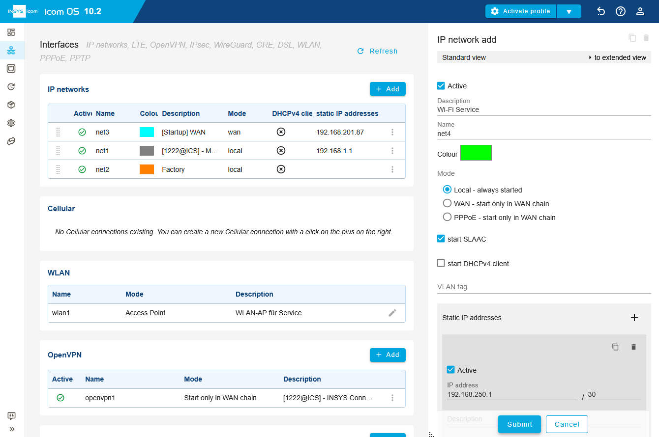
Click on Submit.
Configure the DHCP server.
Click on the Network → DHCP page in the DHCP server section behind the active DHCP server on → to edit this and configure this accordingly:Interface: select the previously created Wi-Fi service network
First IP address: 192.168.250.2
Last IP address: 192.168.250.2
Netmask: 30
Click on Submit.
Add a new firewall rule that permits Wi-Fi access to the local network via HTTPS.
Click on the Network → Firewall / NAT page in the IP-Filter section on and configure it as follows:Description: Wi-Fi - local access via HTTPS
Packet direction: INPUT
IP version: Alle
Protocol: TCP
Input interface: net4
Destination port: 443
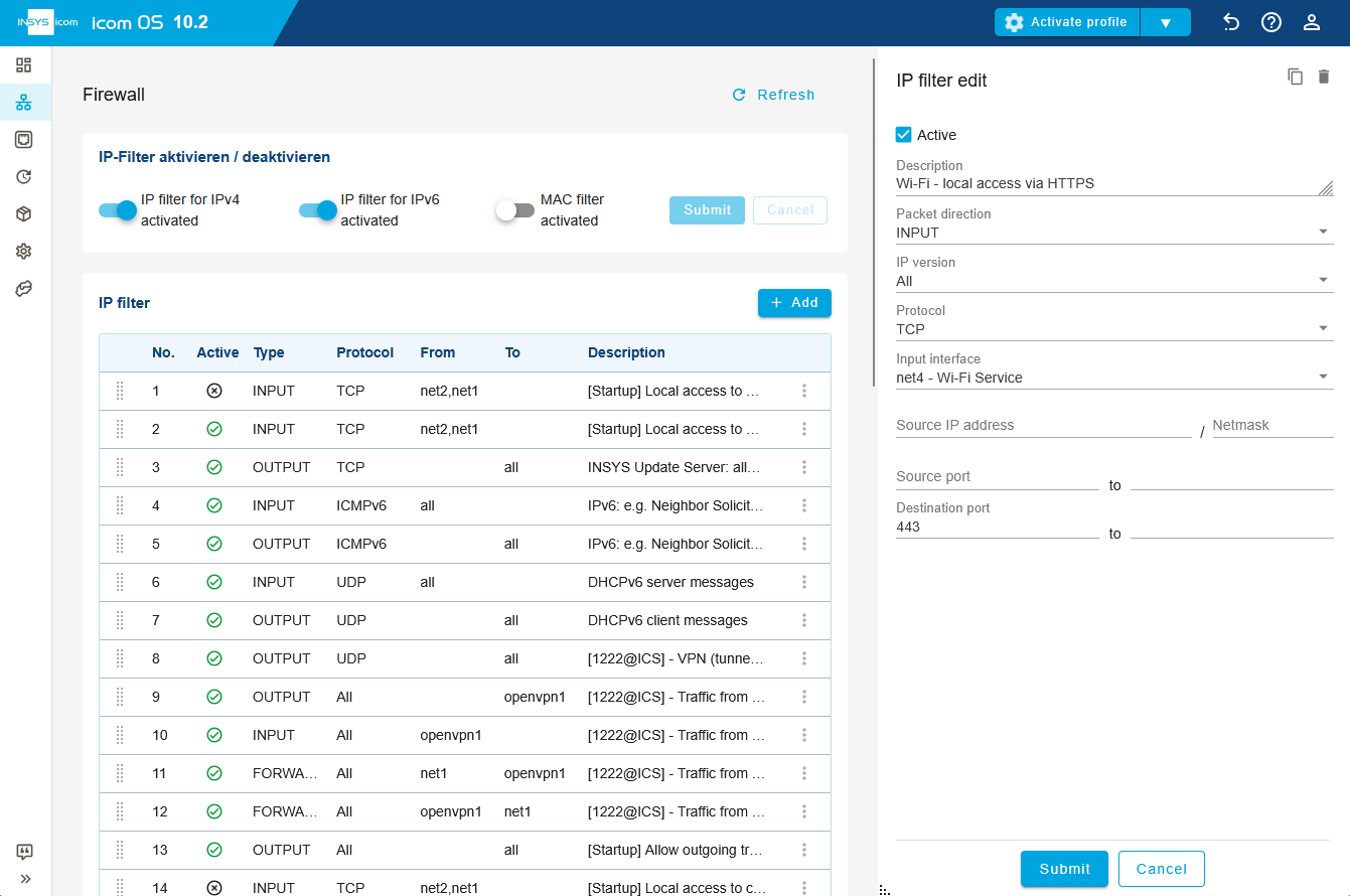
Click on Submit.
Add a new firewall rule that forwards packets from the Wi-Fi network to the local network.
Click on the Network → Firewall / NAT page in the IP-Filter section on and configure it as follows:Description: Wi-Fi traffic between Wi-Fi and machine network
Packet direction: FORWARD
IP version: All
Protocol: All
Input interface: net4
Output interface: net1
Click on Submit.
Add a new firewall rule that permits incoming DHCP-connections from the Wi-Fi network.
Click on the Network → Firewall / NAT page in the IP-Filter section on and configure it as follows:Description: Wi-Fi - DHCP access
Packet direction: INPUT
IP version: All
Protocol: UDP
Input interface: net4
Destination port: 67
Click on Submit.
Add a new firewall rule that permits outgoing DHCP connections to the Wi-Fi network.
Click on the Network → Firewall / NAT page in the IP-Filter section on and configure it as follows:Beschreibung: Wi-Fi - DHCP response
Packet direction: OUTPUT
IP version: All
Protocol: UDP
Output interface: net4
Destination port: 68
Click on Submit.
Add a new firewall rule that permits Pings to the router from the Wi-Fi network.
Click on the Network → Firewall / NAT page in the IP-Filter section on and configure it as follows:Description: Wi-Fi - ping router
Packet direction: INPUT
IP version: IPv4
Protocol: ICMP
Input interface: net4
Click on Submit.
Add a new Source NAT rule that permits masquerading for the Wi-Fi network.
Click on the Network → Firewall / NAT page in the Source NAT section behind Masquerading for all local interfaces on → and add under Output interface the Wi-Fi interface net4.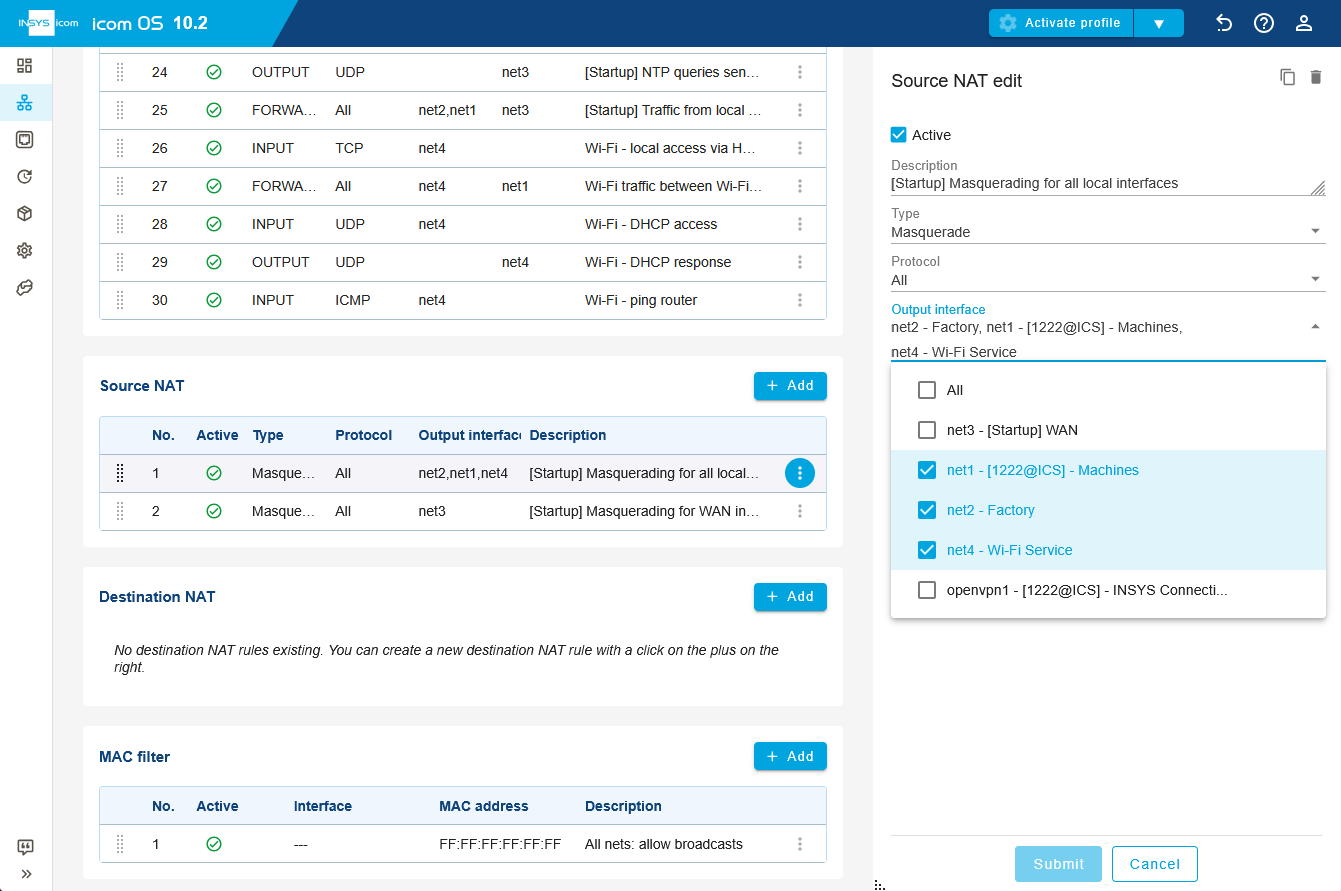
Click on Submit.
Configure the Wi-Fi network.
Click on the Network → Interfaces page in the WLAN section behind the Wi-Fi interface on to edit this and configure this accordingly:Active:
Description: Wi-Fi AP for service
Operation mode: Access Point
Access Point activation only via WLAN button:
Deactivate after (minutes): 30
SSID: Service_1234
Encryption Method: Pre-Shared-Key
Pre-Shared-Key: enter a strong and secure Wi-Fi password
Frequency Band: select the desired Wi-Fi frequency band
Channel: automatic
Bridge to IP net: net2
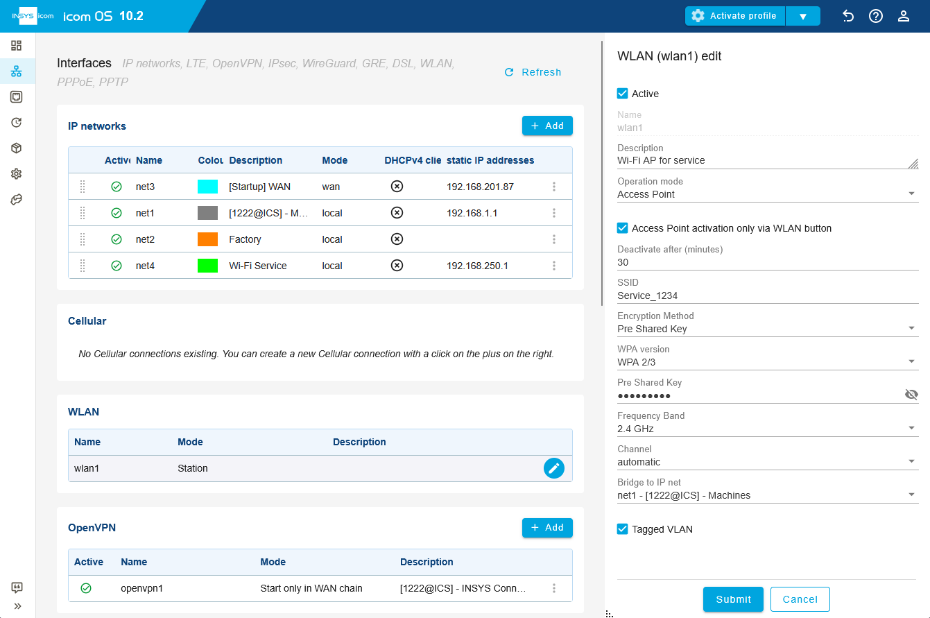
Click on Submit.
Activate the profile with a click on Activate profile .
You have now configured the router for the temporary service Wi-Fi network.
Results check
Enabling and disabling the Wi-Fi connection
Press the WLAN button on the router.
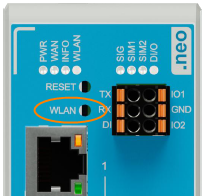
The WLAN LED should start flashing orange and the Wi-Fi will be enabled for the specified duration. Pressing the WLAN button again will disable the WiFi.
Search for the router’s Wi-Fi network on your computer and connect to it. Enter the Pre-shared key specified above.
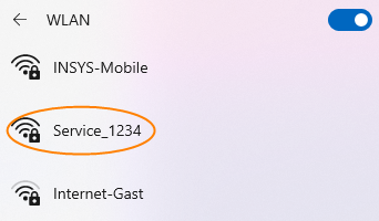
Once the connection has been established, the WLAN LED should light up green.
After the specified time has expired, the Wi-Fi should be deactivated and the WLAN LED should no longer be lit.
If you click on the  Status → Dashboard page in the Network configuration section on the net4 field, you can view detailed information about the Wi-Fi connection. You can check the remaining duration of the Wi-Fi connection under Deactivate after.
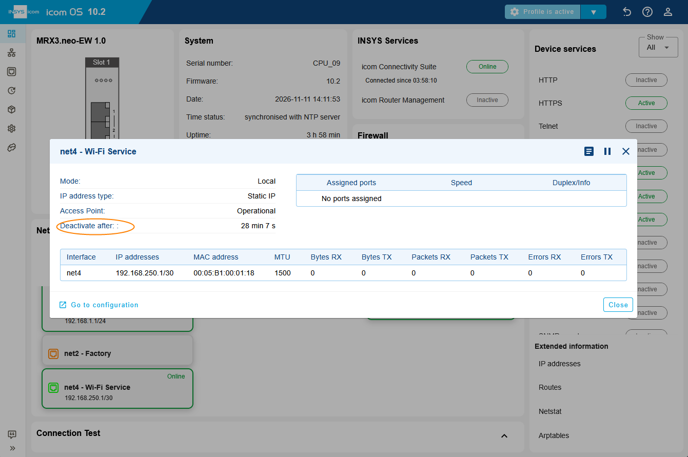
You can view detailed information in the respective logs on the Status → Log view page.
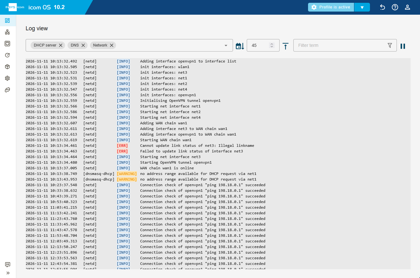
Access to the router and the machine network
Check that the devices on the machine network are accessible by pinging them from the computer connected to the router’s Wi-Fi network.
Troubleshooting
Can’t connect to the Wi-Fi?
Is the WLAN LED flashing? If not, press the WLAN button again or check the Wi-Fi settings.
Is the Wi-Fi SSID visible? If not, check the compatibility of the band you are using (2.4/5 GHz) or the Wi-Fi settings.
Is authentication not possible? Check the pre-shared key set in the Wi-Fi settings.
Is the DHCP client enabled on your PC so that the PC can be assigned an address by the Wi-Fi access point’s DHCP server?
Do you have a Wi-Fi connection but cannot access the devices on the system network?
Check the firewall and NAT rules (IP filters and S-NAT/masquerade).
Is the destination IP address reachable? Ping the destination IP from the computer and the router (Status → Dashboard → Connection Test).
Is your connection unstable?
Reduce the distance between your computer and the router or Wi-Fi access point.
Check for possible sources of interference, such as other radio devices or obstacles that may block reception.
Optimise the position of the antenna.
If necessary, change the frequency band or channel.