Netfilters
The netfilters in the router manipulate and block all data packets on their way from the sender interface to the destination interface as shown in the following sketch. The netfilters consist of NAT (Network Address Translation) and IP filter (Firewall) rules.
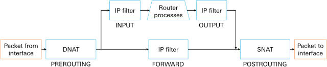
All data packets arriving at the interface pass through all destination NAT (DNAT) rules of the table PREROUTING in sequence and will then be manipulated and forwarded accordingly when the first rule applies.
All data packets not directed to the router run through the rules of the Filter table of the FORWARD chain and will be allowed to pass (are permitted to pass the firewall) as soon as a rule applies. This is the case for example, if a locally connected device sends data to the Internet.
All data packets directed to the router run through the rules of the Filter table of the INPUT chain and will be allowed to pass (are permitted to pass the firewall) to the router as soon as a rule applies. This is the case for example, if the web interface of the router is accessed or the DHCP or VPN server of the router is contacted.
All data packets generated by the router run through the rules of the Filter table of the OUTPUT chain and will be allowed to pass (are permitted to pass the firewall) as soon as a rule applies. This is the case for example, if the router makes NTP or DNS requests or initiates a tunnel.
All data packets which leave the chains OUTPUT and FORWARD, pass through all source NAT (SNAT) rules of the table POSTROUTING in sequence and will then be manipulated and forwarded to the interface accordingly when the first rule applies.
The netfilter rules defined in the router can be displayed in the Dashboard with a click on → Status Information.
Example for a NAT rule for port forwarding
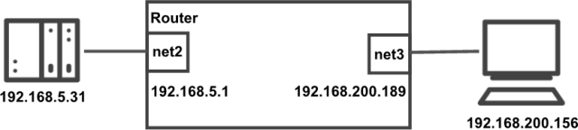
A control (IP address 192.168.5.31) in the machine network (net2) shall be accessed via the local company network (net3) from a PC (IP address 192.168.200.156). The communication port is TCP port 102. The router is the link between both networks and has the IP address 192.168.5.1 in the machine network and the IP address 192.168.200.189 in the company network. The PC in the company network addresses the company network address of the router (192.168.200.189); everything else will be done by the router. A destination NAT rule and an IP filter rule are necessary for this.
The destination NAT rule (port forwarding rule) must be defined as follows:
Description: Forward to control
Type: Portforward
Protocol: TCP
Input interface: net3 (over which the packet reaches the router)
Destination port: 102
Destination NAT to address: 192.168.5.31
Destination NAT to port: 102
The IP filter rule (firewall rule) must be defined as follows:
Description: Forward to control
Packet direction: FORWARD
IP version: all
Protocol: TCP
Input interface: net3 (over which the packet reaches the router)
Output interface: net2 (over which the packet leaves the router)
Source IP address: 192.168.200.156 / 32
Source port: (field remains empty)
Destination IP address: 192.168.5.31 / 32
Destination port: 102
Please note!
Port forwarding is only necessary if no routing for the machine network is configured from the company network.
The device in the company network communicates always with the company network address of the router and not with the machine network address of the control.
No source port is entered in the IP filter rule since this will be determined dynamically by the respective device and is not predictable therefore.
If it shall be possible to access the control from more than one device in the company network, the field Source IP address must be modified. Two examples for this:
Source IP address: 192.168.200.0 / 24 (permits all devices from the company network: IP addresses 192.168.200.1 to 192.168.200.254)
Source IP address: 192.168.200.64 / 26 (permits the following devices from the company network: IP addresses 192.168.200.65 to 192.168.200.126)
The IP address over which the router receives the packet (192.168.200.189) is not used as Destination IP address of the IP filter rule, but the IP address modified by the DNAT rule (192.165.5.31), because the DNAT rule is applied before the IP filter rule.
INSYS Network Info Tool for calculating IP addresses and netmasks
Examples for typical IP filter (Firewall) rules
A few exemplary IP filter (Firewall) rules as they are also created by the wizards are shown in the following. If you want to commission your router without wizard support, you can use these rules as a guide depending on the application.
Rules for general router functions (already present in default settings)
active | Type | IP version | Protocol | from | to | Description | Comment |
|---|---|---|---|---|---|---|---|
INPUT | all | TCP | net1 | port: 80 | Config port: allow HTTP interface | Allows local access to the web interface via HTTP | |
✔ | INPUT | all | TCP | net1 | port: 443 | Config port: allow HTTPS interface | Allows local access to the web interface via HTTPS |
✔ | OUTPUT | all | TCP | all, port: 443 | INSYS Update Server: allow HTTPS | Enables FW download from update server |
Rules for general router functions
active | Type | IP version | Protocol | from | to | Description | Comment |
|---|---|---|---|---|---|---|---|
INPUT | all | TCP | net1, net2 | port: 22 | Local access to command line via SSH | Allows local access to the CLI via SSH | |
✔ | INPUT | all | ICMP | net1, net2 | ICMP pings from the local net | Enables to "ping" the participants in the local network | |
✔ | INPUT | all | UDP | net1 | port: 67 | DHCP queries from the local net | Enables to receive DHCP requests from the local network - necessary, if the router shall act as DHCP server |
✔ | INPUT | all | UDP | net1, net2 | port: 53 | DNS queries from the local net | Enables to receive DNS requests from the local network - necessary, if the router shall act as DNS relay |
✔ | INPUT | all | TCP | net1, net2 | port: 53 | DNS queries from the local net | Enables to receive DNS requests from the local network - necessary, if the router shall act as DNS relay |
INPUT | all | UDP | net1, net2 | port: 123 | NTP queries from the local net | Enables to receive NTP requests from the local network - necessary, if the router shall act as NTP time server | |
✔ | OUTPUT | all | UDP | net1, port: 68 | DHCP responses to the local net | Enables DHCP replies in the local network - necessary, if the router shall act as DHCP server | |
✔ | OUTPUT | all | UDP | lte2, port: 53 | DNS queries sent by the router | Enables DNS requests of the router in the WAN (cellular connection via lte2) - necessary, if the router shall act as DNS relay | |
✔ | OUTPUT | all | TCP | lte2, port: 53 | DNS queries sent by the router | Enables DNS requests of the router in the WAN (cellular connection via lte2) - necessary, if the router shall act as DNS relay | |
✔ | OUTPUT | all | UDP | lte2, port: 123 | NTP queries sent by the router | Enables NTP requests of the router in the WAN (cellular connection via lte2) - necessary, if the router shall update its system time | |
✔ | OUTPUT | all | UDP | net3, port: 53 | DNS queries sent by the router | Enables DNS requests of the router in the WAN (network connection via net3) - necessary, if the router shall act as DNS relay | |
✔ | OUTPUT | all | TCP | net3, port: 53 | DNS queries sent by the router | Enables DNS requests of the router in the WAN (network connection via net3) - necessary, if the router shall act as DNS relay | |
✔ | OUTPUT | all | UDP | net3, port: 123 | NTP queries sent by the router | Enables NTP requests of the router in the WAN (network connection via net3) - necessary, if the router shall update its system time |
Rules for the communication between the networks and the WAN
active | Type | IP version | Protocol | from | to | Description | Comment |
|---|---|---|---|---|---|---|---|
✔ | FORWARD | all | all | net1, net2 | net1, net2 | Traffic between the local nets | Enables communication between the networks net1 and net2 |
✔ | FORWARD | all | all | net1, net2 | lte2 | Traffic from local net into the WAN | Enables the communication between the networks net1 or net2 and the WAN (cellular connection via lte2) |
✔ | FORWARD | all | all | net1, net2 | net3 | Traffic from local net into the WAN | Enables the communication between the networks net1 or net2 and the WAN (network connection via net3) |
Rules for OpenVPN connections to the icom Connectivity Suite
active | Type | IP version | Protocol | from | to | Description | Comment |
|---|---|---|---|---|---|---|---|
✔ | OUTPUT | all | UDP | port: 2043 | OpenVPN (tunnel establishment) | Enables to establish VPN connections to the icom Connectivity Suite and key exchange | |
✔ | OUTPUT | all | all | openvpn1 | Traffic through the OpenVPN tunnel sent by the router | Enables to send all data through VPN tunnel openvpn1 | |
✔ | INPUT | all | all | openvpn1 | Traffic through the OpenVPN tunnel to the router | Enables to receive all data through VPN tunnel openvpn1 | |
✔ | FORWARD | all | all | net1 | openvpn1 | Traffic from the local net1 through the OpenVPN tunnel | Enables to route all data from the local network net1 through VPN tunnel openvpn1 |
✔ | FORWARD | all | all | net2 | openvpn1 | Traffic from the local net2 through the OpenVPN tunnel | Enables to route all data from the local network net2 through VPN tunnel openvpn1 |
✔ | FORWARD | all | all | openvpn1 | net1 | Traffic through the OpenVPN tunnel to the local net1 | Enables to route all data through VPN tunnel openvpn1 into the local network net1 |
✔ | FORWARD | all | all | openvpn1 | net2 | Traffic through the OpenVPN tunnel to the local net2 | Enables to route all data through VPN tunnel openvpn1 into the local network net2 |
Rules for OpenVPN connections
active | Type | IP version | Protocol | from | to | Description | Comment |
|---|---|---|---|---|---|---|---|
✔ | OUTPUT | all | UDP | port: 1194 | lte2, port: 1194 | OpenVPN (tunnel establishment) | Enables to establish VPN connections and key exchange |
✔ | OUTPUT | all | all | openvpn1 | Traffic through the OpenVPN tunnel sent by the router | Enables to send all data through VPN tunnel openvpn1 | |
✔ | INPUT | all | all | openvpn1 | Traffic through the OpenVPN tunnel to the router | Enables to receive all data through VPN tunnel openvpn1 | |
✔ | FORWARD | all | all | net1, net2 | openvpn1 | Traffic from the local net through the OpenVPN tunnel | Enables to route all data from the local networks net 1 or net2 through VPN tunnel openvpn1 |
✔ | FORWARD | all | all | openvpn1 | net1, net2 | Traffic through the OpenVPN tunnel to the local net | Enables to route all data through VPN tunnel openvpn1 into the local networks net1 or net2 |
Rules for IPsec connections
active | Type | IP version | Protocol | from | to | Description | Comment |
|---|---|---|---|---|---|---|---|
✔ | OUTPUT | all | UDP | lte2, port: 500 | IPsec (tunnel establishment) | Enables to establish IPsec connections and key exchange (cellular connection via lte2) | |
✔ | OUTPUT | all | ESP | lte2 | IPsec protocol ESP | Enables IPsec tunnel establishment (cellular connection via lte2) | |
✔ | OUTPUT | all | UDP | lte2, port: 4500 | IPsec UDP Port 4500 (NAT traversal) | Enables to establish IPsec connections and key exchange when using NAT traversal (cellular connection via lte2) | |
✔ | INPUT | all | UDP | lte2 | port: 500 | IPsec (tunnel establishment) | Enables to establish IPsec connections and key exchange (cellular connection via lte2) |
✔ | INPUT | all | ESP | lte2 | IPsec protocol ESP | Enables IPsec tunnel establishment (cellular connection via lte2) | |
✔ | INPUT | all | UDP | lte2 | port: 4500 | IPsec UDP Port 4500 (NAT traversal) | Enables to establish IPsec connections and key exchange when using NAT traversal (cellular connection via lte2) |
✔ | OUTPUT | all | UDP | net3, port: 500 | IPsec (tunnel establishment) | Enables to establish IPsec connections and key exchange (network connection via net3) | |
✔ | OUTPUT | all | ESP | net3 | IPsec protocol ESP | Enables IPsec tunnel establishment (network connection via net3) | |
✔ | OUTPUT | all | UDP | net3, port: 4500 | IPsec UDP Port 4500 (NAT traversal) | Enables to establish IPsec connections and key exchange when using NAT traversal (network connection via net3) | |
✔ | INPUT | all | UDP | net3 | port: 500 | IPsec (tunnel establishment) | Enables to establish IPsec connections and key exchange (network connection via net3) |
✔ | INPUT | all | ESP | net3 | IPsec protocol ESP | Enables IPsec tunnel establishment (network connection via net3) | |
✔ | INPUT | all | UDP | net3 | port: 4500 | IPsec UDP Port 4500 (NAT traversal) | Enables to establish IPsec connections and key exchange when using NAT traversal (network connection via net3) |
✔ | OUTPUT | all | all | ipsec1 | Traffic through the IPsec tunnel sent by the router | Enables to send all data through IPsec tunnel ipsec1 | |
✔ | INPUT | all | all | ipsec1 | Traffic through the IPsec tunnel to the router | Enables to receive all data through IPsec tunnel ipsec1 | |
✔ | FORWARD | all | all | net1, net2 | ipsec1 | Traffic from the local net through the IPsec tunnel | Enables to route all data from the local networks net 1 or net2 through IPsec tunnel ipsec1 |
✔ | FORWARD | all | all | ipsec1 | net1, net2 | Traffic through the IPsec tunnel to the local net | Enables to route all data through IPsec tunnel ipsec1 into the |
MAC filter
A MAC filter is a security function that controls the access to the network using the MAC address of the devices in the network. The MAC address is a hardware address and serves for the positive identification of a network adapter. This allows to restrict the data traffic to certain network devices and the individual IP networks of the router. Only the data traffic via Ethernet connections is restricted with this, connections through tunnels or via cellular radio for example will not be restricted with this. It must be observed for routed connections between two network devices that the MAC addresses of both participants must be permitted.
Security limits: The user should be aware that the actually unique MAC address of a device in the network can be modified with (depending on the device) little effort. If the MAC address of a certain device in the network is permitted, this means that another device can also penetrate the MAC filter, if the permitted MAC address is assigned to it. It is important to remember that MAC filters are only applied when routing across networks and do not block data traffic in the own network.
Default settings contain one MAC filter rule already that permits data traffic with the MAC address FF:FF:FF:FF:FF:FF to all IP networks of the router. The MAC address FF:FF:FF:FF:FF:FF is the broadcast address for ARP (Address Resolution Protocol). Without this rule and activated MAC filters, no ARP requests would be possible for example that are used by the router to determine the assignment between IP and MAC address of the network devices.